What are phasors [solved] 2. figure 1 shows the phasor diagram for a reactive circuit Active and reactive power, phasor diagram, examples
Power Factor Ac Circuit
Phasor power system basic Power factor ac circuit Phasor reactive
Electrical power explained – part 3: balanced three-phase ac power
[solved] 2. figure 1 shows the phasor diagram for a reactive circuitWhat is a power triangle? active, reactive & apparent power Phasors tikz circuits rlc parallelRc parallel circuit (power factor, active and reactive power.
What is power factor in rlc circuitAggregate 125+ draw phasor diagram Phasor diagram of transferring active and reactive powersWhat is active, reactive and apparent power.

Phasor diagram with reactive power support.
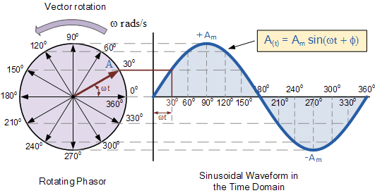
Phasor diagrams of ac circuitsWave current alternating phasor sine ac voltage phasors representation diagrams diagram circuit rotating explanation power waveforms electronics circuits physics electrical Reactive inverter apparent pv factorPhasor diagrams for ac circuits / phasor diagram at r, l and c in ac.
Phasor diagram phasors angle diagrams algebra electronics tutorials degrees ac gif addition circuits measured ws sameFor a purely inductive ac circuit show that the current lags the Three phase star connection (y): three phase power,voltage,currentActive vs reactive power – x-engineer.org.

Answered: 1. is it possible to determine the…
Phase phasor diagram line star connection voltages voltage three current power wye showing electrical electric fig electricalacademiaWhat is a power triangle? active, reactive & apparent power Phasor diagram of capacitorActive, reactive & apparent power.
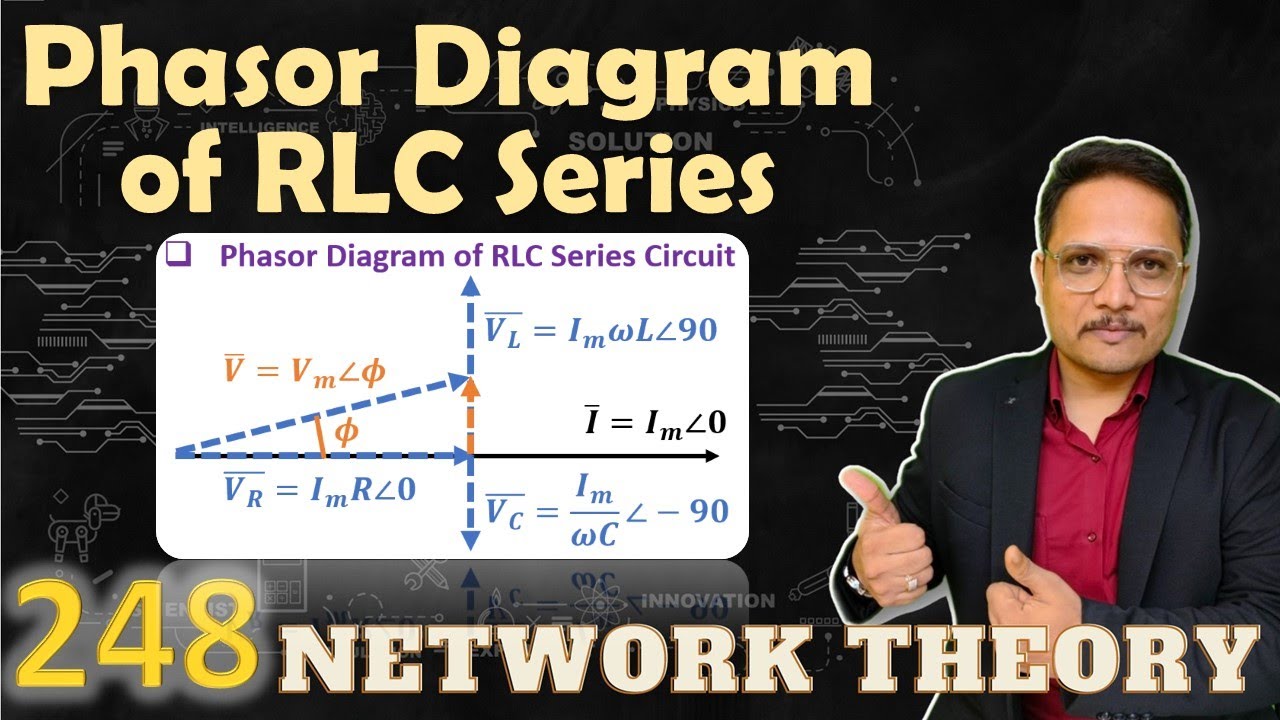
Phasor diagramResistive phasor reactive capacitive apparent mixture Phasor diagrams and phasor algebra used in ac circuitsPhasor diagram of rlc series circuit.

Ac circuit phasors – tikz.net
Phasor diagram phase diagrams ppt sinusoidal algebra balanced three voltage powerpoint presentation frequency magnitude voltagesPhasor representation of active and reactive powers of the protected Phasor interpretation of the reactive power paradox.Phasor reactive transferring powers compensation rpc amount.
Reactive active power apparent current diagram phasor voltage angle circuit definitionInductive triangle phasor reactive voltage capacitive apparent draws rl Do you know what reactive power compensation is? if not, keep readingPhasor diagram of rlc circuit.
Phasor diagrams phasors circuits
Electrical – the potential difference between primary and secondaryActive-reactive power plane for a single-phase pv inverter. the Phasor reactive representation powers feeder u0 oscillation polarization fault positiveSolved 1) draw active and reactive and apparent power phasor.
.


Power Factor Ac Circuit

Three Phase Star Connection (Y): Three Phase Power,Voltage,Current

Active, Reactive & Apparent Power - Electrical Paathshala

For a purely inductive ac circuit show that the current lags the
Phasor Diagrams and Phasor Algebra used in AC Circuits

phasor diagram of rlc circuit - Wiring Diagram and Schematics

Answered: 1. Is it possible to determine the… | bartleby
